Difference between revisions of "Raspdancer"
m (→Intro) |
|||
| (17 intermediate revisions by the same user not shown) | |||
| Line 1: | Line 1: | ||
| − | == |
+ | ==Intro== |
| − | Merging [[Facedancer |
+ | Merging [[Facedancer|Facedancer11 and Facedancer21]] with [[Raspberry Pi]] |
| + | <br>See [https://speakerdeck.com/doegox/raspdancer my presentation] at Hackito 2013. |
||
| − | ===Why?=== |
||
| + | |||
| + | ==Status== |
||
| + | [[#Code|Code]] tested successfully with the Raspdancer11. |
||
| + | <br>[[#Raspdancer11 PCB board|Raspdancer11 PCB]] not tested yet. [[#Raspdancer11 First proto|Raspdancer11 prototype]] successfully tested. |
||
| + | <br>[[#Raspdancer21 PCB board|Raspdancer21 PCB]] not tested yet, design not tested. |
||
| + | |||
| + | ==Rationale== |
||
Facedancer11 and Facedancer21 are one-purpose versions of the flexible GoodFET board. |
Facedancer11 and Facedancer21 are one-purpose versions of the flexible GoodFET board. |
||
<br>It was well designed to move all the intelligence into the host controller, not in the embedded uC. |
<br>It was well designed to move all the intelligence into the host controller, not in the embedded uC. |
||
| Line 28: | Line 35: | ||
And we get a fully autonomous facedancer which can be even powered over USB and controlled remotely |
And we get a fully autonomous facedancer which can be even powered over USB and controlled remotely |
||
| + | ==Code== |
||
| − | ===Schematics for Raspdancer11=== |
||
| − | <pre> |
||
| − | MAX Signal RPi Signal |
||
| − | P3 Vcc P17 3v3 \ 0.1uF -- GND |
||
| − | P4 Vcc P17 3v3 / |
||
| − | P5 GND P25 GND |
||
| − | P6 GND P25 GND |
||
| − | P10 -RES P15 GPIO22 |
||
| − | P11 SCLK P23 SCLK |
||
| − | P12 -SS P24 CE0 |
||
| − | P13 MISO P21 MISO |
||
| − | P14 MOSI P19 MOSI |
||
| − | P15 GPX P16 GPIO23 (currently not connected and not used) |
||
| − | P17 INT P18 GPIO24 (currently not connected and not used) |
||
| − | P18 GND P25 GND |
||
| − | P19 GND P25 GND ---------- USB conn GND |
||
| − | P20 D- ----------- R33 -- USB conn D- |
||
| − | P21 D+ ----------- R33 -- USB conn D+ |
||
| − | P22 Vcc P17 3v3 |
||
| − | P23 Vcc P17 3v3 |
||
| − | P24 VBCOMP ------------------ USB conn Vcc -- 1uF -- GND |
||
| − | P26 XI ------------Xtal1- 18pF -- GND |
||
| − | P27 XO ------------Xtal2- 18pF -- GND |
||
| − | </pre> |
||
| − | One can also connect MAX_P24 VBCOMP to RPi_P4 5V0 to power directly the RPi via this USB entry but beware: |
||
| − | * you're fuzzing the one which is powering you, don't cry if you experience power losses... |
||
| − | * the polyfuse is left out, you can re-introduce a polyfuse 1A 6V (but being powered from a *real* USB port should be fine) |
||
| − | [[File:Raspdancer11_v10_sch.png|600px]] |
||
| − | ===Components for Raspdancer11=== |
||
| − | Name Package Description |
||
| − | IC1 LQFP32 MAX3420E |
||
| − | R1 0603 33R USB Serie Resistor |
||
| − | R2 0603 33R USB Serie Resistor |
||
| − | C1 0603 1.0µF Capacitor |
||
| − | C2 0603 0.1µF Decoupling Capacitor |
||
| − | C3 0603 18pF Capacitor |
||
| − | C4 0603 18pF Capacitor |
||
| − | C5 0603 1.0µF Capacitor |
||
| − | Q1 5x3.2 12MHz SMD Crystal, 18pF (see note) |
||
| − | USB USB Mini Receptacle e.g. UX60-MB-5ST |
||
| − | J_RASP 2x13 Receptacle, 2.54mm, 26way (see note) |
||
| − | |||
| − | Notes: comparing to the components reused from the original Facedancer, differences are: |
||
| − | * smaller crystal package |
||
| − | * 2x13 connector towards RPi, e.g. a SAMTEC BCS-113-L-D-TE, or even a smaller conn as 2x6 is enough, but be the sure to plug the board correctly into the larger connector! |
||
| − | |||
| − | ===First proto of Raspdancer11=== |
||
| − | Using a TQFP32 to DIP32 PCB adapter from http://www.ett.co.th/ and a regular through-hole crystal |
||
| − | |||
| − | [[File:Raspdancer-proto1.jpg|400px]] |
||
| − | [[File:Raspdancer-proto1-full.jpg|400px]] |
||
| − | ===PCB boards for Raspdancer11 & Raspdancer21=== |
||
| − | Thanks to Jean-Christophe Nicaise for his help! |
||
| − | <br>I didn't touch Eagle for so many years ^^ |
||
| − | <br>[[File:Raspdancer11_v10_brd.png|300px]][[File:Raspdancer21_v10_brd.png|300px]] |
||
| − | <br>'''Left: Raspdancer11 with MAX3420E, right: Raspdancer21 with MAX3421E''' |
||
| − | <br>Jumpers & connectors: |
||
| − | * JP1: Jumper to get powered over USB (PoUSB) |
||
| − | * JP2: Solder jumper to wire INT to GPIO24 in case we'll need it |
||
| − | * JP3 (Raspdancer11): Some pads to allow soldering directly a USB cable instead of using a USB connector |
||
| − | * Raspdancer21: USB A female header |
||
| − | * JP4: Solder jumper to wire GPX to GPIO23 in case we'll need it |
||
| − | * J_RASP: Should work (except PoUSB) with a 2x6 connector instead of 2x13 |
||
| − | |||
| − | ===Code=== |
||
Travis did an amazing job at building a Python library and examples for the MAX3420E & MAX3421E, let's reuse them! |
Travis did an amazing job at building a Python library and examples for the MAX3420E & MAX3421E, let's reuse them! |
||
<br>You'll need to get [[Raspberry_Pi#GPIO|GPIO Python support]] and [[Raspberry_Pi#SPI|SPI Python support]] for your Raspberry Pi. |
<br>You'll need to get [[Raspberry_Pi#GPIO|GPIO Python support]] and [[Raspberry_Pi#SPI|SPI Python support]] for your Raspberry Pi. |
||
| Line 140: | Line 83: | ||
</source> |
</source> |
||
| − | + | ==Sources== |
|
All hardware (Eagle sch & brd, Gerber files) and software (GoodFET.py) sources are now available directly in Travis' SVN repository: |
All hardware (Eagle sch & brd, Gerber files) and software (GoodFET.py) sources are now available directly in Travis' SVN repository: |
||
* http://sourceforge.net/p/goodfet/code/HEAD/tree/contrib/facedancer/raspdancer/ |
* http://sourceforge.net/p/goodfet/code/HEAD/tree/contrib/facedancer/raspdancer/ |
||
| + | ==Raspdancer11== |
||
| + | ===Raspdancer11 Schematics=== |
||
| + | One can optionally connect MAX_P24 VBCOMP to RPi_P4 5V0 to power directly the RPi via this USB entry but beware: |
||
| + | * you're fuzzing the one which is powering you, don't cry if you experience power losses... |
||
| + | * the polyfuse is left out, you can re-introduce a polyfuse 1A 6V (but being powered from a *real* USB port should be fine) |
||
| + | [[File:Raspdancer11_v10_sch.png]] |
||
| + | ===Raspdancer11 Components=== |
||
| + | Name Package Description |
||
| + | IC1 LQFP32-08 MAX3420E |
||
| + | R1 0603 33Ω Resistor |
||
| + | R2 0603 33Ω Resistor |
||
| + | C1 0603 1.0µF Capacitor |
||
| + | C2 0603 0.1µF Decoupling Capacitor |
||
| + | C3 0603 18pF Capacitor |
||
| + | C4 0603 18pF Capacitor |
||
| + | Q1 5x3.2 12MHz SMD Crystal, 18pF (see note) |
||
| + | USB USB MiniB USB-MiniB Receptacle e.g. UX60-MB-5ST |
||
| + | J_RASP 2x13 Receptacle, 2.54mm, 26way (see note) |
||
| + | |||
| + | Notes: comparing to the components reused from the original Facedancer11, differences are: |
||
| + | * smaller crystal package |
||
| + | * 2x13 connector towards RPi, e.g. a SAMTEC BCS-113-L-D-TE, or even a smaller conn as 2x6 is enough if you don't use the power-over-USB feature, but be the sure to plug the board correctly into the larger connector! |
||
| + | * one 1.0µF capacitor was left out, as it was left out later with the Facedancer21 design. |
||
| + | |||
| + | ===Raspdancer11 First proto=== |
||
| + | Using a TQFP32 to DIP32 PCB adapter from http://www.ett.co.th/ and a regular through-hole crystal |
||
| + | |||
| + | [[File:Raspdancer-proto1.jpg|400px]] |
||
| + | [[File:Raspdancer-proto1-full.jpg|400px]] |
||
| + | ===Raspdancer11 PCB board=== |
||
| + | Thanks to Jean-Christophe Nicaise and Zac Franken for their help! |
||
| + | <br>I didn't touch Eagle for so many years ^^ |
||
| + | <br>[[File:Raspdancer11_v10_brd.png|300px]] [[File:Raspdancer11_v10_brd_filled.png|300px]] |
||
| + | <br>Jumpers & connectors: |
||
| + | * JP1: Jumper to get powered over USB (PoUSB) |
||
| + | * JP2: Solder jumper to wire INT to GPIO24 in case we'll need it |
||
| + | * JP3: Some pads to allow soldering directly a USB cable instead of using a USB connector |
||
| + | * JP4: Solder jumper to wire GPX to GPIO23 in case we'll need it |
||
| + | * J_RASP: Should work (except PoUSB) with a 2x6 connector instead of 2x13 |
||
| + | |||
| + | ==Raspdancer21== |
||
| + | ===Raspdancer21 Schematics=== |
||
| + | One can optionally connect MAX_P24 VBCOMP to RPi_P4 5V0 to power directly the RPi via this USB entry when using the raspdancer21 as USB peripheral but beware: |
||
| + | * you're fuzzing the one which is powering you, don't cry if you experience power losses... |
||
| + | * the polyfuse is left out, you can re-introduce a polyfuse 1A 6V (but being powered from a *real* USB port should be fine) |
||
| + | [[File:Raspdancer21_v10_sch.png]] |
||
| + | ===Raspdancer21 Components=== |
||
| + | Name Package Description |
||
| + | IC1 TQFP32-5mm MAX3421E |
||
| + | R1 0603 33Ω Resistor |
||
| + | R2 0603 33Ω Resistor |
||
| + | C1 0603 1.0µF Capacitor |
||
| + | C2 0603 0.1µF Decoupling Capacitor |
||
| + | C3 0603 18pF Capacitor |
||
| + | C4 0603 18pF Capacitor |
||
| + | Q1 5x3.2 12MHz SMD Crystal, 18pF (see note) |
||
| + | USB1 USB MiniB USB-MiniB Receptacle e.g. UX60-MB-5ST |
||
| + | USB2 USB A USB-A SMT CONN Receptacle |
||
| + | J_RASP 2x13 Receptacle, 2.54mm, 26way (see note) |
||
| + | |||
| + | Notes: comparing to the components reused from the original Facedancer21, differences are: |
||
| + | * smaller crystal package |
||
| + | * 2x13 connector towards RPi, e.g. a SAMTEC BCS-113-L-D-TE, or even a smaller conn as 2x6 is enough if you don't use the power-over-USB feature, but be the sure to plug the board correctly into the larger connector! |
||
| + | |||
| + | ===Raspdancer21 PCB board=== |
||
| + | <br>[[File:Raspdancer21_v10_brd.png|300px]] [[File:Raspdancer21_v10_brd_filled.png|300px]] |
||
| + | <br>Jumpers & connectors: |
||
| + | * JP1: Jumper to get powered over USB (PoUSB) |
||
| + | * JP2: Solder jumper to wire INT to GPIO24 in case we'll need it |
||
| + | * JP4: Solder jumper to wire GPX to GPIO23 in case we'll need it |
||
| + | * J_RASP: Should work (except PoUSB) with a 2x6 connector instead of 2x13 |
||
| + | * USB A female connector on the other side of the PCB |
||
| + | |||
| + | ==Derivatives== |
||
| + | Dominic Spill ported it to the BeagleBoard and created the [https://github.com/dominicgs/BeagleDancer BeagleDancer] |
||
| + | ==Contacts== |
||
| + | For any suggestion or question, feel free to [[User:PhilippeTeuwen|contact me]] |
||
Latest revision as of 13:58, 21 February 2016
Intro
Merging Facedancer11 and Facedancer21 with Raspberry Pi
See my presentation at Hackito 2013.
Status
Code tested successfully with the Raspdancer11.
Raspdancer11 PCB not tested yet. Raspdancer11 prototype successfully tested.
Raspdancer21 PCB not tested yet, design not tested.
Rationale
Facedancer11 and Facedancer21 are one-purpose versions of the flexible GoodFET board.
It was well designed to move all the intelligence into the host controller, not in the embedded uC.
Facedancer11 hardware can be seen as:
USBconn -- FT232RL -- MSP430F2618TPM -- MAX3420E -- USBconn
where the first two chips are only converting busses:
 USBconn -- FT232RL -- MSP430F2618TPM -- MAX3420E -- USBconn
         USB   <>   UART     <>       SPI   ...   (USB)
BoM view (Farnell prices with tax):
 USBconn -- FT232RL -- MSP430F2618TPM -- MAX3420E -- USBconn
 USBconn +  6.60€   +  15.80€         +  10.00€    +  USBconn
So 22.40€ to talk SPI over UART over USB while the Raspberry-Pi has natively SPI, hmmm.
Bus speed view: yes there is a kind of bottleneck there...
 USBconn -- FT232RL -- MSP430F2618TPM -- MAX3420E -- USBconn
        12MB/s      115200bauds       26MHz
Let's try to make a RPi extension board with only the MAX3420E.
And to save a few cents and construction pain let's replace the USB connector by a USB cable from a cannibalized mouse.
So:
RPI-MODA-256M -- MAX3420E -- USBcable
From a BoM point of view this becomes (depending on which RPi, what you add to the RPi, nice casing etc):
                        RPI-MODA-256M -- MAX3420E -- USBcable
                        33.50€        +  10.00€
Bus speed view:
                        RPI-MODA-256M -- MAX3420E -- USBcable
                                      26MHz
And we get a fully autonomous facedancer which can be even powered over USB and controlled remotely
Code
Travis did an amazing job at building a Python library and examples for the MAX3420E & MAX3421E, let's reuse them!
You'll need to get GPIO Python support and SPI Python support for your Raspberry Pi.
From the original facedancer code, you'll need GoodFETMAXUSB.py and the goodfet.maxusb* scripts
Then instead of the original GoodFET.py library, use [{{#file: GoodFET.py}} this GoodFET.py version]:
#!/usr/bin/env python
# (C) 2013 Philippe Teuwen <phil at teuwen.org>

import spi
import RPi.GPIO as GPIO

class GoodFET:
    data=""
    def __init__(self, *args, **kargs):
        GPIO.setmode(GPIO.BOARD)
        # pin15=GPIO22 is linked to MAX3420 -RST
        GPIO.setup(15, GPIO.OUT)
        GPIO.output(15,GPIO.LOW)
        GPIO.output(15,GPIO.HIGH)
        spi.openSPI(speed=26000000)
    def __del__(self):
        spi.closeSPI()
        GPIO.output(15,GPIO.LOW)
        GPIO.output(15,GPIO.HIGH)
        GPIO.cleanup()
    def writecmd(self, app, verb, count=0, data=[]):
        if verb: # ignore all but R/W cmd
            return
        if isinstance(data,str):
            data = [ord(x) for x in data]
        data = tuple(data)
        data = spi.transfer(data)
        self.data = "".join([chr(x) for x in data])
    def serInit(self):
        pass
There are probably better ways to integrate it into the GoodFET software stack but with this small code snippet, you can take the latest great GoodFETMAXUSB.py and goodfet.maxusb* python scripts and just drop them along this GoodFET.py, without need for re-applying any patch.
Note that with the raspdancer, goodfet.maxusbhid is becoming too fast and I'm missing the beginning of the injected string. I had to add some initial "NoEvent / key up" chars ("\x00" * 20) in typestring() in GoodFETMAXUSB.py:
def typestring(self):
    if self.typestrings.has_key(self.OsLastConfigType):
    return ("\x00" * 20) + self.typestrings[self.OsLastConfigType];
else:
    return ("\x00" * 20) + self.typestrings[-1];
Sources
All hardware (Eagle sch & brd, Gerber files) and software (GoodFET.py) sources are now available directly in Travis' SVN repository:
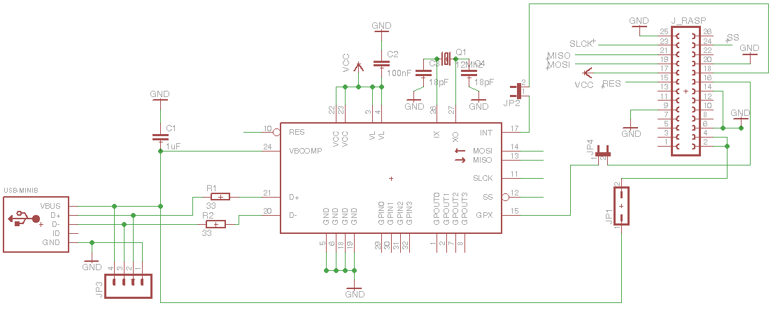
Raspdancer11
Raspdancer11 Schematics
One can optionally connect MAX_P24 VBCOMP to RPi_P4 5V0 to power directly the RPi via this USB entry but beware:
- you're fuzzing the one which is powering you, don't cry if you experience power losses...
- the polyfuse is left out, you can re-introduce a polyfuse 1A 6V (but being powered from a *real* USB port should be fine)
Raspdancer11 Components
Name   Package    Description
IC1    LQFP32-08  MAX3420E
R1     0603       33Ω Resistor
R2     0603       33Ω Resistor
C1     0603       1.0µF Capacitor
C2     0603       0.1µF Decoupling Capacitor
C3     0603       18pF Capacitor
C4     0603       18pF Capacitor
Q1     5x3.2      12MHz SMD Crystal, 18pF      (see note)
USB    USB MiniB  USB-MiniB Receptacle e.g. UX60-MB-5ST
J_RASP 2x13       Receptacle, 2.54mm, 26way    (see note)
Notes: comparing to the components reused from the original Facedancer11, differences are:
- smaller crystal package
- 2x13 connector towards RPi, e.g. a SAMTEC BCS-113-L-D-TE, or even a smaller conn as 2x6 is enough if you don't use the power-over-USB feature, but be the sure to plug the board correctly into the larger connector!
- one 1.0µF capacitor was left out, as it was left out later with the Facedancer21 design.
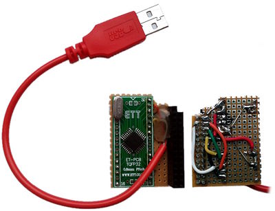
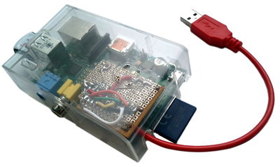
Raspdancer11 First proto
Using a TQFP32 to DIP32 PCB adapter from http://www.ett.co.th/ and a regular through-hole crystal
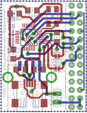
Raspdancer11 PCB board
Thanks to Jean-Christophe Nicaise and Zac Franken for their help!
I didn't touch Eagle for so many years ^^
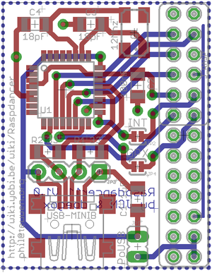
Jumpers & connectors:
- JP1: Jumper to get powered over USB (PoUSB)
- JP2: Solder jumper to wire INT to GPIO24 in case we'll need it
- JP3: Some pads to allow soldering directly a USB cable instead of using a USB connector
- JP4: Solder jumper to wire GPX to GPIO23 in case we'll need it
- J_RASP: Should work (except PoUSB) with a 2x6 connector instead of 2x13
Raspdancer21
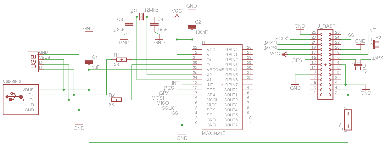
Raspdancer21 Schematics
One can optionally connect MAX_P24 VBCOMP to RPi_P4 5V0 to power directly the RPi via this USB entry when using the raspdancer21 as USB peripheral but beware:
- you're fuzzing the one which is powering you, don't cry if you experience power losses...
- the polyfuse is left out, you can re-introduce a polyfuse 1A 6V (but being powered from a *real* USB port should be fine)
Raspdancer21 Components
Name   Package    Description
IC1    TQFP32-5mm MAX3421E
R1     0603       33Ω Resistor
R2     0603       33Ω Resistor
C1     0603       1.0µF Capacitor
C2     0603       0.1µF Decoupling Capacitor
C3     0603       18pF Capacitor
C4     0603       18pF Capacitor
Q1     5x3.2      12MHz SMD Crystal, 18pF      (see note)
USB1   USB MiniB  USB-MiniB Receptacle e.g. UX60-MB-5ST
USB2   USB A      USB-A SMT CONN Receptacle
J_RASP 2x13       Receptacle, 2.54mm, 26way    (see note)
Notes: comparing to the components reused from the original Facedancer21, differences are:
- smaller crystal package
- 2x13 connector towards RPi, e.g. a SAMTEC BCS-113-L-D-TE, or even a smaller conn as 2x6 is enough if you don't use the power-over-USB feature, but be the sure to plug the board correctly into the larger connector!
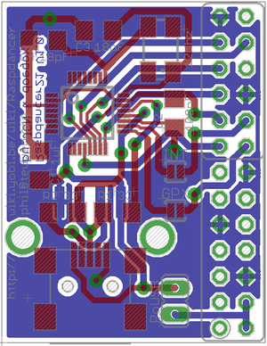
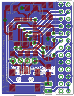
Raspdancer21 PCB board
- JP1: Jumper to get powered over USB (PoUSB)
- JP2: Solder jumper to wire INT to GPIO24 in case we'll need it
- JP4: Solder jumper to wire GPX to GPIO23 in case we'll need it
- J_RASP: Should work (except PoUSB) with a 2x6 connector instead of 2x13
- USB A female connector on the other side of the PCB
Derivatives
Dominic Spill ported it to the BeagleBoard and created the BeagleDancer
Contacts
For any suggestion or question, feel free to contact me
