Difference between revisions of "PNG Merge"
m (→Examples) |
m (→Challenge 3) |
||
| (29 intermediate revisions by the same user not shown) | |||
| Line 17: | Line 17: | ||
==Literate programming== |
==Literate programming== |
||
| − | + | [{{#filelink: mergeRGBi.py}} mergeRGBi.py (available for download here)] can do the job: |
|
{{#fileanchor: mergeRGBi.py}} |
{{#fileanchor: mergeRGBi.py}} |
||
<source lang=python> |
<source lang=python> |
||
| Line 250: | Line 250: | ||
==Examples== |
==Examples== |
||
===Poc||GTFO0x06=== |
===Poc||GTFO0x06=== |
||
| − | Here is an example given in [[PoC_or_GTFO|PoC||GTFO]] by @angealbertini |
+ | Here is an example given in [[PoC_or_GTFO|PoC||GTFO]] by @angealbertini mixing a [https://en.wikipedia.org/wiki/Pallas's_cat manul] (@sergeybratus mascot) with Pastor Manul Laphroaig. |
<br>[[Image:Pocorgtfo6_1.png|link=http://wiki.yobi.be/images/f/f8/Pocorgtfo6_1.png]] |
<br>[[Image:Pocorgtfo6_1.png|link=http://wiki.yobi.be/images/f/f8/Pocorgtfo6_1.png]] |
||
<br>Click on the image to download the original version. |
<br>Click on the image to download the original version. |
||
| Line 278: | Line 278: | ||
<br>[[Image:Pocorgtfo6_1_snapshot.png]] |
<br>[[Image:Pocorgtfo6_1_snapshot.png]] |
||
<br>Original indexed images (pastor and palette) were simply black & white with a 2-color palette and now the palette image is used as a 256-color palette for the pastor. |
<br>Original indexed images (pastor and palette) were simply black & white with a 2-color palette and now the palette image is used as a 256-color palette for the pastor. |
||
| + | |||
===Poc||GTFO0x06 variant=== |
===Poc||GTFO0x06 variant=== |
||
We've seen that we can change the size of the indexed image such that scanlines will coincide. |
We've seen that we can change the size of the indexed image such that scanlines will coincide. |
||
| Line 296: | Line 297: | ||
</pre> |
</pre> |
||
Here is the result, a file which is now 100% compatible with libpng or other PNG readers, no more filter byte or IDAT size issues: |
Here is the result, a file which is now 100% compatible with libpng or other PNG readers, no more filter byte or IDAT size issues: |
||
| − | <br>[[Image:Pocorgtfo6_2_result.png|link=http://wiki.yobi.be/images/9/96/Pocorgtfo6_2_result.png]] |
+ | <br>[[Image:Pocorgtfo6_2_result.png|link=http://wiki.yobi.be/images/9/96/Pocorgtfo6_2_result.png|600px]] |
| + | <br>We've reduced it's display because it's now 3x larger than the RGB image. |
||
| − | |||
| − | ==Gray== |
+ | ===Gray palette=== |
| − | The introductory snapshot is another example, based on a crop from https://www.flickr.com/photos/scytale/5357607697 |
+ | The introductory snapshot is another example by Ange and I, based on a crop from https://www.flickr.com/photos/scytale/5357607697 |
<br>[[Image:Tabasco.png|link=http://wiki.yobi.be/images/4/4c/Tabasco.png]] |
<br>[[Image:Tabasco.png|link=http://wiki.yobi.be/images/4/4c/Tabasco.png]] |
||
<br>Click on the image to download the original version. |
<br>Click on the image to download the original version. |
||
| Line 305: | Line 306: | ||
<br>[[Image:Pngmerge_what_snapshot.png]] |
<br>[[Image:Pngmerge_what_snapshot.png]] |
||
<br>The palette was constructed in a way that each of the 4 tones appear regularly, at least once per line, to avoid distortions when adjusting the RGB components to find suitable indexes. |
<br>The palette was constructed in a way that each of the 4 tones appear regularly, at least once per line, to avoid distortions when adjusting the RGB components to find suitable indexes. |
||
| + | |||
| + | ===Steganalysis-resistant=== |
||
| + | In the code I mentioned a little tweak to make the PoC steganalysis-resistant. |
||
| + | <br>Let's explain it: |
||
| + | <br>If we don't provide an explicit 16x16 palette, the code creates a palette from the original small palette. Let's use the corkami image presented in the previous example without a palette image. If we created the 16x16 palette just by duplicating the 4-color palette we would get a very regular pattern, as on the left of this snapshot: |
||
| + | <br>[[Image:Pngmerge-stegano-plte.png]] |
||
| + | <br>While on the right we see the actual palette produced by our code. |
||
| + | <br>The difference is that, for the left palette, e.g. all light gray indexes will have the value 0, 4, 8, 12, ... so all multiple of 4 which means that the index bytes in IDAT will always have their 2 last bits equal to 0b00 and a contrario the dark indexes modulo 4 will always be =3 so last 2 bits will be equal to 0b11. |
||
| + | <br>The result is that the indexed image can be easily revealed with steganalysis tools, here with [http://www.caesum.com/handbook/stego.htm StegSolve]: |
||
| + | <br><br>[[Image:Pngmerge-stegano.png]] |
||
| + | <br><br>While for the image on the right, nothing can be seen in the LSB (except for some scanline filter bytes that happen to be present on top of a uniform area near the top left corner). |
||
| + | <br><br>I cannot share @reversity 's original hand-crafted PoC but it was not steganalysis-resistant, here a crop of the top left: |
||
| + | <br>[[Image:Reversity-stegano.png]] |
||
| + | ===Pixel mapping=== |
||
| + | The steganalysis seen in previous section helps also to understand how RBG pixels are mapped to the indexed image pixels. |
||
| + | <br>Each RGB pixel will "produce" 3 indexed pixels so if the indexed image is of the same size as the RGB one, it will actually occupy only 1/3 of the RGB IDAT. |
||
| + | <br>Let's look at e.g. pixel (261,21) on the RGB image: |
||
| + | <br>[[Image:tabasco_stegano.png]] |
||
| + | <br>It maps to pixel (340,64) on the indexed image because both share the same data in the IDAT bytestream (not forgetting the 1 filter byte at start of each scanline): |
||
| + | * RGB pixel(261,21): (1+3*'''261''')+('''21'''*(1+3*400))=26005 |
||
| + | * indexed pixel (340,64): (1+'''340''')+('''64'''*(1+400))=26005 |
||
| + | This schema by Ange helps understanding both IDAT values interpretations: |
||
| + | <br>[[Image:MergeRGBillustrated_cropped.png|500px]] |
||
| + | |||
| + | ===Challenge=== |
||
| + | Here is another one with a 5-color palette, you can try to find the hidden image by yourself: |
||
| + | <br>[[Image:Tabasco-4c.png|link=http://wiki.yobi.be/images/a/a9/Tabasco-4c.png]] |
||
| + | <br>You'll need to: |
||
| + | * patch the color type byte |
||
| + | * patch the width |
||
| + | * patch the IHDR CRC |
||
| + | Here is the palette I used, magnified 10x: |
||
| + | <br>[[Image:Tabasco-4c-palx10.png]] |
||
| + | |||
| + | ===Challenge 2=== |
||
| + | Here is another one by Ange featuring [https://www.sba-research.org/wp-content/uploads/2014/12/qrinception.png QR Inception] by Adrian Dabrowsky et al. |
||
| + | <br>But I came across and hide yet another 2D barcode in the third image, can you find the hidden word? |
||
| + | <br>[[Image:Incincinception.png|link=http://wiki.yobi.be/images/d/df/Incincinception.png]] |
||
| + | <!-- http://datamatrix.kaywa.com/img.php?s=1&d=xxxxxxx --> |
||
| + | ===Challenge 3=== |
||
| + | Actually there is a trick to minimize the patches to apply while maintaining a perfect compatibility with the standard: |
||
| + | <br>Instead of starting from a RGB image, let's start from a 8-bit Greyscale image. |
||
| + | <br>So one pixel from the greyscale image will correspond to one pixel of the indexed image, no more need for patching image size or dealing with scanline filter bytes! |
||
| + | <br>Here is such example, all you have to reveal the indexed image is to patch the color byte from 0 to 3 and the IHDR CRC. |
||
| + | <br><br>[[Image:Manul_laphroaig.png|link=http://wiki.yobi.be/images/d/d1/Manul_laphroaig.png]] |
||
| + | <br><br>The 8-color palette, magnified: |
||
| + | <br>[[Image:Pal_8c2_x10.png]] |
||
==PNG fix CRC== |
==PNG fix CRC== |
||
| Line 339: | Line 387: | ||
<br>See http://www.joshmillard.com/2007/10/04/retro-histo-making-an-image-fit-your-histogram/ and http://www.ironicsans.com/2007/09/idea_the_histogram_as_the_imag.html |
<br>See http://www.joshmillard.com/2007/10/04/retro-histo-making-an-image-fit-your-histogram/ and http://www.ironicsans.com/2007/09/idea_the_histogram_as_the_imag.html |
||
<br>But the method would have to be integrated without destroying our careful rgb values<>indexes correspondences... |
<br>But the method would have to be integrated without destroying our careful rgb values<>indexes correspondences... |
||
| + | |||
| + | Actually histogram is useful to detect that some manipulation was done on part of the image, e.g. taking again the example given as introduction, we know the indexed image is embedded in the first 1/3 of the image. Let's compare its histogram with the lower 2/3: |
||
| + | <br>[[Image:Tabasco_what_histo.png]] |
||
Latest revision as of 01:29, 20 January 2015
How many images in this PNG?
This is a Poc (Proof of Concept) to create a PNG file that contains different images somehow entangled together.
The original idea is from @reversity who proposed us a hand-crafted PoC.
There was no available script to play with so @angealbertini and I tried to reverse-engineer it :-)
The idea is that PNG data can be interpreted depending on the Color Type among other types as RGB values (color type =2) or as indexed values (color type =3) together with a palette (PLTE).
RGB PNG (color type =2) can legitimately contain a PLTE, from the specs:
If present, it provides a suggested set of from 1 to 256 colors to which the truecolor image can be quantized if the viewer cannot display truecolor directly.
Which means nowadays that a PLTE in a RGB image will be systematically ignored!
So just by changing the color type byte (typically the 25th byte) from 2 to 3 (and the IHDR CRC) we can change completely the way the image is displayed.
To craft such image, we need a RGB image, an indexed image and the corresponding palette which, we'll see, can also contain an image!
Here is one example:

Literate programming
[{{#filelink: mergeRGBi.py}} mergeRGBi.py (available for download here)] can do the job: {{#fileanchor: mergeRGBi.py}}
#!/usr/bin/env python
# Ange Albertini, Philippe Teuwen, BSD Licence, 2014
# Based on Dominique Bongard original idea

# Should we restrict scanline filters to 0 only?
# Needed e.g. for Gimp under Windows
# Side effect is presence of black diagonals in results
SLF_FIX=False
This SLF_FIX refers already to an obscure problem in Gimp under Windows but let's ignore it for now.
_pngread and _pngmake are two helper functions to... read and make PNG structures and handle them as list of chunks:
{{#fileanchor: mergeRGBi.py}}
import struct, sys, zlib, binascii

_MAGIC = "\x89PNG\x0d\x0a\x1a\x0a"
_crc32 = lambda d:(binascii.crc32(d) % 0x100000000)

def pngread(f):
    """gets a file, returns a list of [type, data] chunks"""
    assert f.read(8) == _MAGIC
    chunks = []
    while (True):
        l, = struct.unpack(">I", f.read(4))
        t = f.read(4)
        d = f.read(l)
        assert _crc32(t + d) == struct.unpack(">I", f.read(4))[0]
        chunks += [[t, d]]
        if t == "IEND":
            return chunks
    raise(BaseException("Invalid image"))

def pngmake(chunks):
    """returns a PNG binary string from a list of [type, data] PNG chunks"""
    s = [_MAGIC]
    for t, d in chunks:
        assert len(t) == 4
        s += [
            struct.pack(">I", len(d)),
            t,
            d,
            struct.pack(">I", _crc32(t + d))
            ]
    return "".join(s)
Usage will be
mergeRGBi.py rgb.png ncol.png result.png
So RGB input chunks are stored in rgb, indexed image input chunks are stored in nc (for N colors) {{#fileanchor: mergeRGBi.py}}
fnrgb, fnnc, fnout = sys.argv[1:4]
with open(fnrgb, "rb") as frgb:
    rgb = pngread(frgb)
with open(fnnc, "rb") as fnc:
    nc = pngread(fnc)
For simplicity, we only support inputs with the minimum number of chunks: IHDR, possibly one PLTE (even for rgb, in case we're reusing a previous PoC file), one single IDAT, and IEND.
We extract width and height of rgb and nc.
{{#fileanchor: mergeRGBi.py}}
assert len(rgb) == 3 or len(rgb) == 4 # IHDR [PLTE] IDAT IEND
assert len(nc) == 4 # IHDR PLTE IDAT IEND
wrgb, hrgb = struct.unpack(">LL", rgb[0][1][0:0 + 4 * 2])
wnc, hnc   = struct.unpack(">LL", nc[0][1][0:0 + 4 * 2])
We also support only unfiltered PNGs. A PNG is made of compressed horizontal scanlines starting with a "filter type" byte according to a "filter method" but as of today only "filter method 0" is standardized with 5 different types of filter, the first one, 0, means the identity function: Filt(x) = Orig(x).
Once decompressed, scanlines are streams of bytes of size=(width*3)+1 for rgb with 3 bytes per pixel and of width+1 for indexed nc.
To embed nc in rgb we must make sure its IDAT contains same or less bytes than rgb IDAT.
{{#fileanchor: mergeRGBi.py}}
print "RGB dimensions:", wrgb, hrgb
print "RGB IDAT:", ((wrgb*3)+1)*hrgb
print "idx dimensions:", wnc, hnc
print "idx IDAT:", (wnc+1)*hnc
assert ((wrgb*3)+1)*hrgb >= (wnc+1)*hnc
Let's decompress scanlines from IDAT {{#fileanchor: mergeRGBi.py}}
px_rgb  = [ord(i) for i in zlib.decompress(rgb[1 if len(rgb) == 3 else 2][1])]
px_nc = [ord(i) for i in zlib.decompress(nc[2][1])]
We extract the palette from nc and count the number of colors (as rgb triplets). By safety we check all indexes are indeed in the range of palette colors. The we convert the palette into a list of rgb triplets. {{#fileanchor: mergeRGBi.py}}
# Initial palette
palin = nc[1][1]
# Number of colors in initial palette
n=len(palin)/3
assert n >= max(px_nc)+1
print "PLTE", n, "colors"
# Convert palette into list of rgb triplets
palin = [palin[i:i+3] for i in range(0, len(palin), 3)]
We can also allow the script to take an extra image as palette. We'll see later that it gives the freedom to put also an image in the palette itself!
So usage becomes:
mergeRGBi.py rgb.png ncol.png result.png [palette.png]
If there is a palette image, it must respect the same constraints as nc and it must be a 16x16 image using the same palette as nc.
All colors present in the palette must be present in the image that will become the new palette.
Ideally all colors should be present in each of the 16 lines of the new palette to avoid too large distortions in the final RGB result.
{{#fileanchor: mergeRGBi.py}}
# New palette
if len(sys.argv)>4:
    # We got a file as new palette
    fnpal = sys.argv[4]
    with open(fnpal, "rb") as fpal:
        pal = pngread(fpal)
    assert len(pal) == 4 # IHDR PLTE IDAT IEND
    assert 16, 16 == struct.unpack(">LL", pal[0][1][0:0 + 4 * 2])
    assert nc[1][1] == pal[1][1]
    px_pal = [ord(i) for i in zlib.decompress(pal[2][1])]
    # Remove scanlines
    for i in xrange(16):
        px_pal.pop(i*16)
    # We need all palette colors
    for i in xrange(n):
        assert i in px_pal
    palout = [palin[i] for i in px_pal]
If we don't provide a new palette, then it will be constructed from the original small palette and it will be extended to cover all 256 possible indexes so we'll have the possibility to tweak rgb pixels towards indexes of wanted colors without too much distortion, again.
Original palette is mutated when duplicated to avoid traditional LSB-based stegano scanners, so indexes of same color won't have always the same LSB.
{{#fileanchor: mergeRGBi.py}}
else:
    palout=[]
    paltmp=palin
    for i in xrange((256/n)+1):
        palout+=paltmp
        # mutate original palette
        paltmp=paltmp[1:]+paltmp[:1]
    palout=palout[:256]
So now how the rgb IDAT is distorted to map to nc? Each r, g, b byte is interpreted as an index when the color type byte is forced =3 and the corresponding color is given by the palette. We've see above that we tried to extend the palette to all 256 possible values by repeating the same colors regularly. So now we need a function that given a starting R or G or B value to be interpreted as index and a desired color, returns the closest index pointing to that color. Special attention must be taken when we're dealing with the start of a scanline, the filter byte, because theoretically it can only be between 0 and 5. And it cannot change otherwise we're changing the applied filtering. Unless rgb and nc have very compatible dimensions, a color byte of rgb can match a filter byte of nc or vice versa. Practically, most applications accept a filter byte >5 and will interpret it as a 0, which gives us some flexibility. But as said earlier, Gimp under Windows is one of the applications complaining about filter byte>5, therefore this SLF_FIX to force filter bytes=0, but this will display unsightly black lines in the counterpart. {{#fileanchor: mergeRGBi.py}}
def find_closest_idx(col, idx, palette, scanline_rgb=False, scanline_nc=False):
    off=0
    if scanline_rgb:
        assert idx == 0 or idx>=5
    if SLF_FIX and (scanline_rgb or scanline_nc):
        return 0
    assert col in palette[5 if scanline_rgb else 0:]
    if scanline_nc and 0<=idx<5:
        return 0 if idx < 3 else 5
    while abs(off) < len(palette):
        if (idx+off == 0 or (5 if (scanline_rgb or scanline_nc) else 0) <= idx+off < len(palette)) \
          and col == palette[idx+off]:
            return idx+off
        else:
            off = -off if off>0 else -off+1
Now all we have is to go over nc pixels and merge them into rgb data. {{#fileanchor: mergeRGBi.py}}
for i, j in enumerate(px_nc):
    # integrate n-col indexes in RGB values, watch out RGB scanlines
    px_rgb[i]=find_closest_idx(palin[j],px_rgb[i], palout,
                               scanline_rgb=(i % (3 * wrgb + 1)) == 0,
                               scanline_nc=(i % (wnc + 1)) == 0)
And we're done! We can pack everything in a PNG. {{#fileanchor: mergeRGBi.py}}
px_final = "".join([chr(i) for i in px_rgb])

outchunks = [
    ["IHDR", rgb[0][1]],
    ["PLTE", ''.join(palout)],
    ["IDAT", zlib.compress(px_final, 9)],
    ["IEND", ""]
    ]

with open(fnout, "wb") as fout:
    fout.write(pngmake(outchunks))
To make analysis easier, we can generate a PNG with the color type patch to see the indexed version. As some applications don't appreciate more bytes than needed in IDAT (as libpng) we truncate IDAT too. {{#fileanchor: mergeRGBi.py}}
outchunks[0][1] = outchunks[0][1][:9] + "\3" + outchunks[0][1][10:]
# Fix size
outchunks[0][1]=struct.pack(">LL", wnc, hnc)+outchunks[0][1][0 + 4 * 2:]
# Optional step: truncate IDAT to make libpng happy:
outchunks[2][1] = zlib.compress(px_final[:(wnc+1)*hnc], 9)
with open("_" + fnout, "wb") as fout:
    fout.write(pngmake(outchunks))
# To debug IDAT:
#with open("_IDAT_" + fnout, "wb") as fout:
#    fout.write(px_final[:(wnc+1)*hnc])
Usage
[{{#filelink: mergeRGBi.py}} mergeRGBi.py is available for download here]
mergeRGBi.py rgb.png ncol.png result.png [palette.png]
It merges a n-color indexed PNG into a RGB PNG.
To find back the indexed PNG, one has to change color=2 -> color=3 in the IHDR, which is already done in secondary output _resultat.png.
Original palette is mutated when duplicated to avoid traditional LSB-based stegano scanners.
But you can provide your own 16x16 PNG to be used as palette. It must have the same palette as the indexed PNG and make sure each line contains each color to avoid too large adjustments in RGB PNG.
Note that libpng will complain about the indexed PNG because IDAT is larger than needed, try e.g. Gimp.
RGB PNG requirements:
- IHDR+IDAT+IEND
- scanline filters=0
n colors PNG requirements:
- IHDR+PLTE+IDAT+IEND
- scanline filters=0
IDAT size <= RGB IDAT size, i.e. (wnc+1)*hnc <= ((wrgb*3)+1)*hrgb
palette PNG requirements:
- IHDR+PLTE+IDAT+IEND
- scanline filters=0
- 16x16
- same palette as n colors PNG
- image must use all colors
To verify and get one single IDAT, you can do:
pngchunks foo.png
advpng -z -0 foo.png
advpng -z -3 foo.png
pngchunks foo.png
Note that if you're in a situation where you need to use SLF_FIX, one way to avoid it is to use a n colors PNG with width exactly = 3*width of RGB PNG.
In that case, scanline filter bytes of rgb and nc will coincide and you won't get dark diagonals, you even don't need to activate this option anymore.
But size of the image will have to be patched too in the IHDR when patching the filter byte.
E.g. you can choose rations such as x/y~=1/(3*x/y) => x/y~=1/sqrt(3) => x/y ~ 0.577
So one can use a RGB PNG of 200x350 pixels (x/y ~ 0.571) and a n-color indexed PNG of 600x350 pixels
Examples
Poc||GTFO0x06
Here is an example given in PoC||GTFO by @angealbertini mixing a manul (@sergeybratus mascot) with Pastor Manul Laphroaig.

Click on the image to download the original version.
pngchunks reveals that there is a PLTE chunk...
Let's patch the color type byte (25th byte) and fix the IHDR CRC:
0000 0000: 89 50 4E 47 0D 0A 1A 0A  00 00 00 0D 49 48 44 52  .PNG.... ....IHDR
0000 0010: 00 00 02 08 00 00 02 78  08 02 00 00 00 8F BC 8C  .......x ........
0000 0020: F5 00 00 03 00 50 4C 54  45 FF FF FF FF FF FF FF  .....PLT E.......
becomes
0000 0000: 89 50 4E 47 0D 0A 1A 0A  00 00 00 0D 49 48 44 52  .PNG.... ....IHDR
0000 0010: 00 00 02 08 00 00 02 78  08 03 00 00 00 37 00 EB  .......x .....7..
0000 0020: 90 00 00 03 00 50 4C 54  45 FF FF FF FF FF FF FF  .....PLT E.......
See below for a code snippet to fix PNG CRCs.
This simple fix is enough to open the manipulated image in Gimp, even if libpng complains a bit:
- libpng warning: Ignoring bad adaptive filter type
- because we've some filter bytes > 5
- libpng warning: Extra compressed data.
libpng warning: Extra compression data.- because the indexed image data is smaller than the RGB data so the actual IDAT is bigger than needed.
- libpng error: IDAT: CRC error
- probably because libpng computes CRC on the expected IDAT size instead of the real chunk size.
Result, including the palette:

Original indexed images (pastor and palette) were simply black & white with a 2-color palette and now the palette image is used as a 256-color palette for the pastor.
Poc||GTFO0x06 variant
We've seen that we can change the size of the indexed image such that scanlines will coincide.
This PoC does exactly that:

Click on the image to download the original version.
Let's patch the color type byte (25th byte), multiply the width by 3 (3*0x208=0x618) and fix the IHDR CRC:
0000 0000: 89 50 4E 47 0D 0A 1A 0A  00 00 00 0D 49 48 44 52  .PNG.... ....IHDR
0000 0010: 00 00 02 08 00 00 02 78  08 02 00 00 00 8F BC 8C  .......x ........
0000 0020: F5 00 00 03 00 50 4C 54  45 FF FF FF FF FF FF FF  .....PLT E.......
becomes now
0000 0000: 89 50 4E 47 0D 0A 1A 0A  00 00 00 0D 49 48 44 52  .PNG.... ....IHDR
0000 0010: 00 00 06 18 00 00 02 78  08 03 00 00 00 A0 77 19  .......x ......w.
0000 0020: FA 00 00 03 00 50 4C 54  45 FF FF FF FF FF FF FF  .....PLT E.......
Here is the result, a file which is now 100% compatible with libpng or other PNG readers, no more filter byte or IDAT size issues:

We've reduced it's display because it's now 3x larger than the RGB image.
Gray palette
The introductory snapshot is another example by Ange and I, based on a crop from https://www.flickr.com/photos/scytale/5357607697

Click on the image to download the original version.
Here the initial corkami and palette share an initial 4-tone palette

The palette was constructed in a way that each of the 4 tones appear regularly, at least once per line, to avoid distortions when adjusting the RGB components to find suitable indexes.
Steganalysis-resistant
In the code I mentioned a little tweak to make the PoC steganalysis-resistant.
Let's explain it:
If we don't provide an explicit 16x16 palette, the code creates a palette from the original small palette. Let's use the corkami image presented in the previous example without a palette image. If we created the 16x16 palette just by duplicating the 4-color palette we would get a very regular pattern, as on the left of this snapshot:

While on the right we see the actual palette produced by our code.
The difference is that, for the left palette, e.g. all light gray indexes will have the value 0, 4, 8, 12, ... so all multiple of 4 which means that the index bytes in IDAT will always have their 2 last bits equal to 0b00 and a contrario the dark indexes modulo 4 will always be =3 so last 2 bits will be equal to 0b11.
The result is that the indexed image can be easily revealed with steganalysis tools, here with StegSolve:

While for the image on the right, nothing can be seen in the LSB (except for some scanline filter bytes that happen to be present on top of a uniform area near the top left corner).
I cannot share @reversity 's original hand-crafted PoC but it was not steganalysis-resistant, here a crop of the top left:

Pixel mapping
The steganalysis seen in previous section helps also to understand how RBG pixels are mapped to the indexed image pixels.
Each RGB pixel will "produce" 3 indexed pixels so if the indexed image is of the same size as the RGB one, it will actually occupy only 1/3 of the RGB IDAT.
Let's look at e.g. pixel (261,21) on the RGB image:

It maps to pixel (340,64) on the indexed image because both share the same data in the IDAT bytestream (not forgetting the 1 filter byte at start of each scanline):
- RGB pixel(261,21): (1+3*261)+(21*(1+3*400))=26005
- indexed pixel (340,64): (1+340)+(64*(1+400))=26005
This schema by Ange helps understanding both IDAT values interpretations:

Challenge
Here is another one with a 5-color palette, you can try to find the hidden image by yourself:

You'll need to:
- patch the color type byte
- patch the width
- patch the IHDR CRC
Here is the palette I used, magnified 10x:

Challenge 2
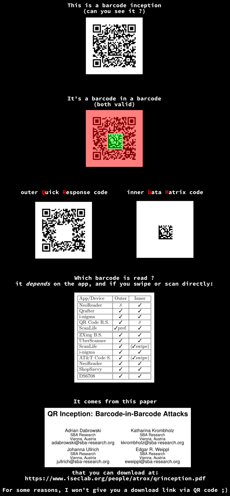
Here is another one by Ange featuring QR Inception by Adrian Dabrowsky et al.
But I came across and hide yet another 2D barcode in the third image, can you find the hidden word?

Challenge 3
Actually there is a trick to minimize the patches to apply while maintaining a perfect compatibility with the standard:
Instead of starting from a RGB image, let's start from a 8-bit Greyscale image.
So one pixel from the greyscale image will correspond to one pixel of the indexed image, no more need for patching image size or dealing with scanline filter bytes!
Here is such example, all you have to reveal the indexed image is to patch the color byte from 0 to 3 and the IHDR CRC.

The 8-color palette, magnified:

PNG fix CRC
Here is some helper code to fix CRC in a PNG:
#!/usr/bin/env python

import struct
import sys
import binascii
PNGSIG = '\x89PNG\r\n\x1a\n'
source_file, result_file = sys.argv[1:3]
with open(source_file, "rb") as f:
    s = f.read()
assert s.startswith(PNGSIG)
r, s = s[:8], s[8:]
while s:
    size,=struct.unpack(">I", s[:4])
    typ, data=s[4:8], s[8:8+size]
    crc,=struct.unpack(">I", s[8+size:8+size+4])
    s=s[8+size+4:]
    calccrc=binascii.crc32(typ+data) % 0x100000000
    if crc != calccrc:
        print "Fixing CRC of", typ
    r+=struct.pack(">I", size)+typ+data+struct.pack(">I", calccrc)
with open(result_file, "wb") as f:
    f.write(r)
Going further?
We managed to put 3 images into 1, could we do better?
Maybe :-)
One can draw e.g. a skyline in the image histogram.
See http://www.joshmillard.com/2007/10/04/retro-histo-making-an-image-fit-your-histogram/ and http://www.ironicsans.com/2007/09/idea_the_histogram_as_the_imag.html
But the method would have to be integrated without destroying our careful rgb values<>indexes correspondences...
Actually histogram is useful to detect that some manipulation was done on part of the image, e.g. taking again the example given as introduction, we know the indexed image is embedded in the first 1/3 of the image. Let's compare its histogram with the lower 2/3:
